|
Soft foot is a common issue when aligning rotating equipment. It is a major cause of repeatability problems in shaft alignment measurements. In addition to alignment quality and repeatability problems, it can be a cause of machinery vibration, reduce life in electric motors, and cause internal clearance problems in gearboxes and pumps. But if the proper precautions are taken, soft foot can be minimized and controlled.. The term “soft foot” is the common term used for the improper contact between a machine casing, and the baseplate used to support it. It may be either an angular or parallel soft foot, but often it is a combination of the two. 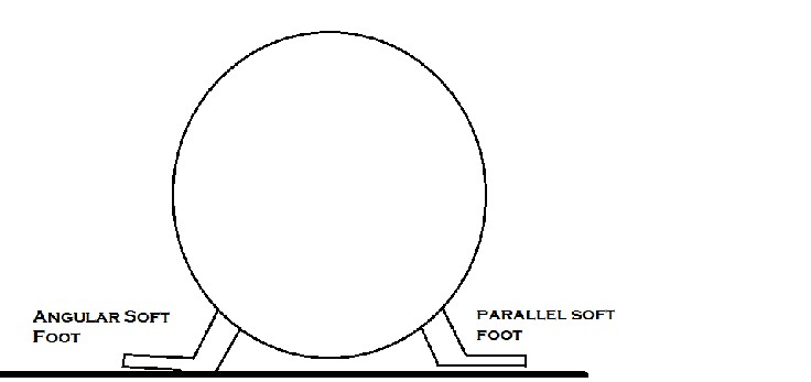
It is often compared to a straight-backed wooden chair, where one leg, being shorter, does not contact the floor, causing a rocking motion in the chair when you are seated in it. While this is a good mental image, soft foot in machinery is a little more complex. While an angular soft foot might make contact with a baseplate or foundation, it does not make a UNIFORM amount of contact. Once base bolts are tightened, the foot tends to bend to conform to the baseplate to which it is mounted. CAUSES OF SOFT FOOT CONDITIONS
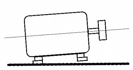
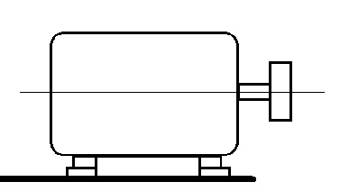
As stated above, soft foot conditions adversely affect alignment quality and repeatability. Here’s how: Regardless of whether you have:
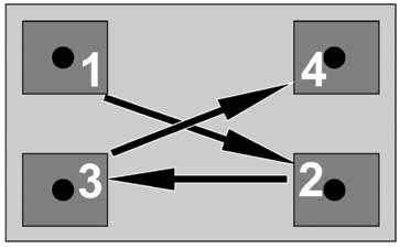
Notice that the relative position of the shaft centerline changes due to changes in the position of the soft foot. In addition, unless you tighten and loosen the bolts in sequence, the position of the shaft centerline in relation to the stationary machine can change. As an example, if you tighten the inboard left foot first one time, and the inboard right foot the second time, you may take measurements in different shaft centerline locations. Using the straight-backed chair analogy, not tightening in a known sequence causes the movable machine to “rock” into different positions. STEPS TO MINIMIZE AND CONTROL SOFT FOOT
0 Comments
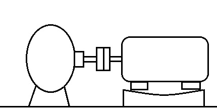
Shaft alignment process is delicate and, needs special tools and training to accomplish the alignment within the allowed tolerances. The errors encountered during this process could be classified as soft-foot, coupling backlash and incorrect bolting sequence while tightening (or loosening) the machine bolts.
Backlash In layman terms, backlash is the angular movement (about its axis) between mating parts in an assembly. Backlash occurs in couplings, v-belt drives, gears and other interfacing components. Backlash is desirable in some cases while controlled synchronous drives try to avoid this phenomenon. Even under desired cases, the maximum backlash value is very less to achieve better efficiency. Flexible couplings usually have inbuilt backlash. Even the products that claims zero backlash conceals the condition at which such zero backlash is achieved. It’s always advisable to speak to technical representative to obtain information required. Under operation, the coupling inserts wear out causing more backlashes. Couplings Neoprene and rubber inserts exhibit excessive twisting or visual tooth wear which is a good caution for shaft aligner. Spider-type couplings exhibit excessive compression of the “spider.” On grid-type couplings, inspect for excessive wear of the “spring” type inserts, as well as wear of the grids. On shim-pack couplings, look for wear of the rubber bushings, as well as breakage of the shim packs. Less likely, but just as important, causes of backlash can be improper hub to shaft fits, or excessive keyway wear. Occasionally, backlash can be caused by loose foot bolts or other bolted components. Backlash can cause erratic shaft alignment values in both dial indicator and laser alignment readings. A backlash of greater than 2° of angular movement should be considered excessive, and should be reduced to less than 2° before alignment begins. Some methods of controlling and minimizing backlash include:. •Replacing the worn or defective components in the system which contributes to excessive backlash, such as worn couplings or inserts. •Minimizing the effects of backlash by rotating shafts to maintain torque at a consistent level and direction. This can be done by rotating the shafts to be measured in a consistent direction, such as clockwise, or counter-clockwise. •Utilizing temporary mechanical means, such as duct tape or mechanic’s wire, to temporarily override the coupling’s ability to experience backlash. Remember, most mating rotational systems have a slight degree of backlash, which is both harmless, and desirable for efficient operation. But excessive backlash can decrease the accuracy of your alignment. Keep it to a minimum.. There are a lot of ways to block ads, but with a simple command in the developer console, you can disable all ads on YouTube via an experiment. Google frequently tries out new features with experiments via TestTube. A less advertised experiment can disable all ads on the site. Here's how to turn it on:
document.cookie="VISITOR_INFO1_LIVE=oKckVSqvaGw; path=/; domain=.youtube.com";window.location.reload();

The above photograph shows the turbulence field behind theHorns Rev 1 offshore wind turbines. Unique meteorological conditions on 12 February 2008 at 1300 hours resulted in the wind turbines creating condensation (i.e. clouds) of the very humid air, thus making it possible to see the turbulence pattern behind the wind turbines.
Source : http://www.ict-aeolus.eu/about.html |
AuthorWith unceasing appetite for knowledge - Karthik Kumarasamy 
Archives
August 2015
Categories
All
|
 RSS Feed
